Installation of Holley Dominator EFI
If you have any questions or comments about this project, please
email me at: ![]()
Click on the thumbnail for a higher resolution picture
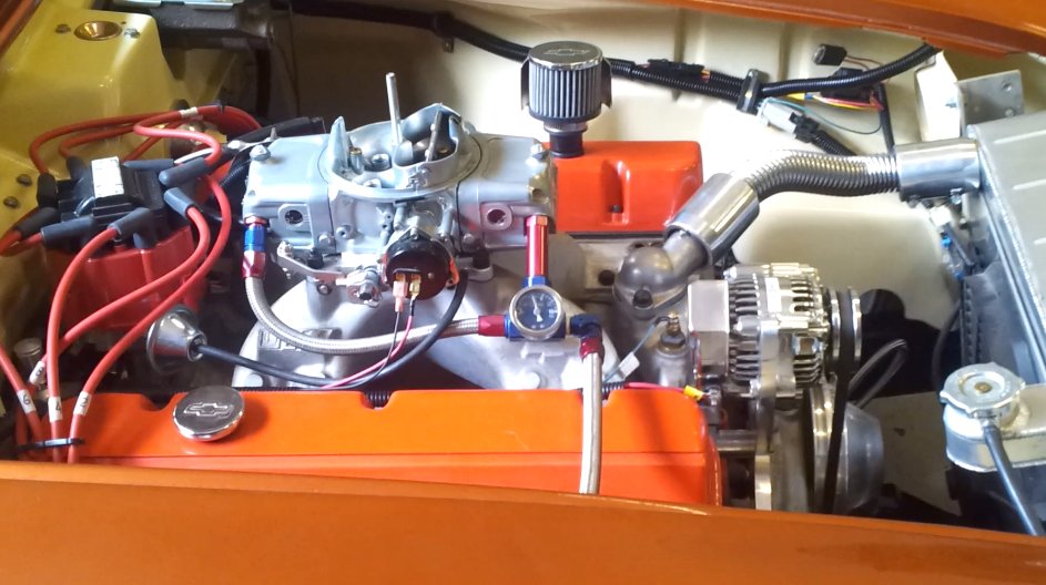
The 572/620 GM crate engine with the 850 CFM Barry Grant Demon carburetor.
When I decided to replace the carburetor system on this engine with an
electronic fuel injection unit I did a lot of research on which system to use. I wanted the system to control the spark advance
and I also wanted fully sequential spark control as opposed to batch fire, this meant that
I would have to have both a crank signal and a cam signal.
My car also has a 4L80E 4 speed electronic transmission which was being controlled by a TCI controller. If possible I wanted the new EFI system to control the transmission.
Another other option I wanted was the ability to reduce the
power of the engine by reducing the spark advance. With
the carbureted engine I had constructed a small microcomputer (Arduino UNO) controlled
circuit which read the front and rear ABS sensors and I wanted to use this device to act
as a traction control to reduce engine power based on the wheel slip differential between
the front and rear wheels.
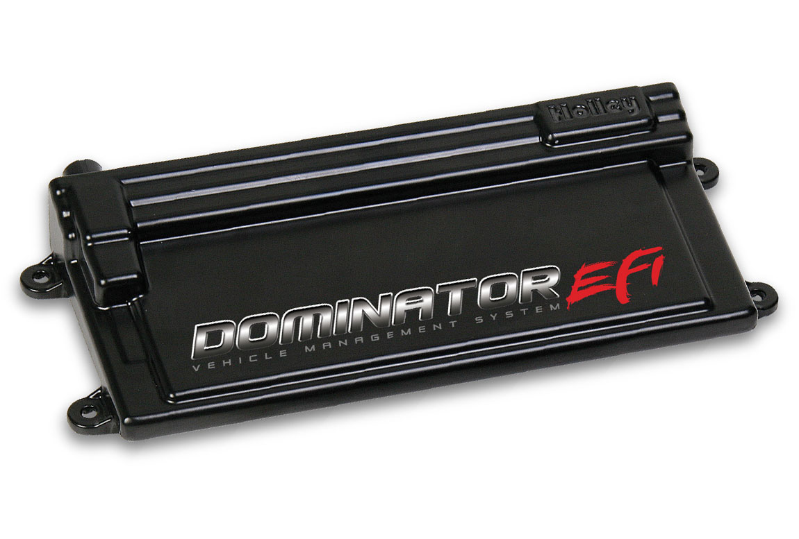
The Holley Dominator system seemed to be the only system that met all of my requirements
Dominator ECU |
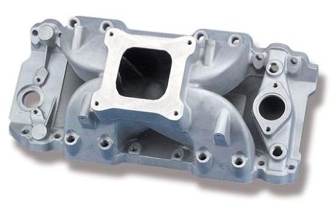
Intake Manifold |
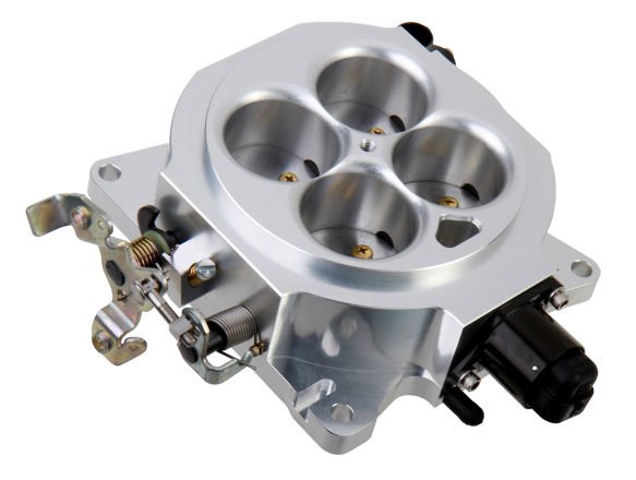
Throttle Body |
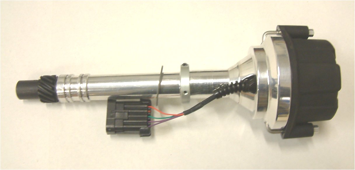
Dual Sync Distributor |
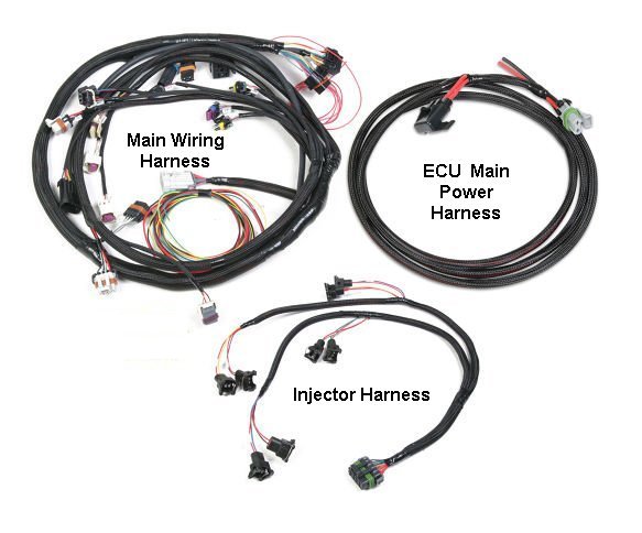
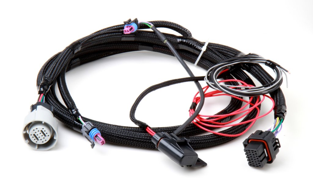
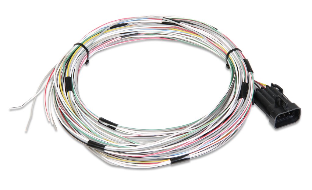
Wiring Harnesses |
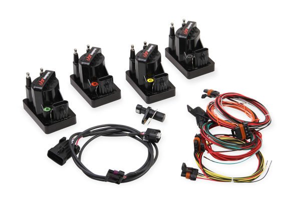
Ignition Coils |
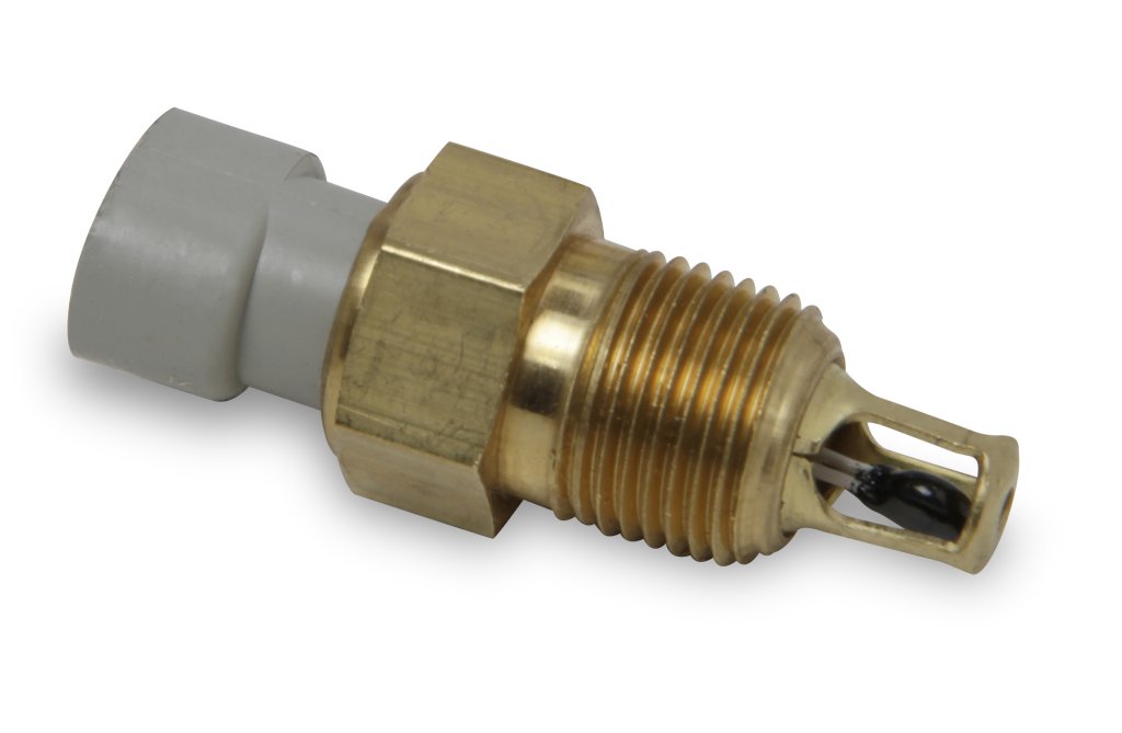
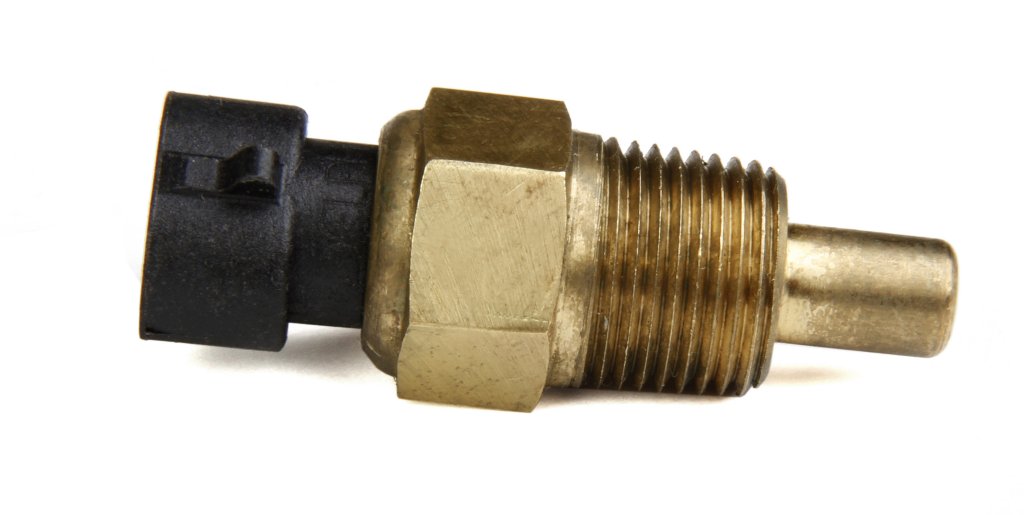
Air Temp Sensor |
Coolant Temp Sensor |
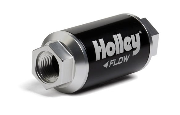
Fuel filters(2) |
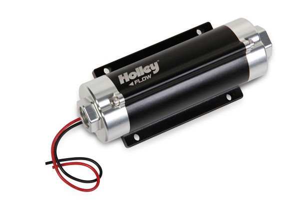
Fuel Pump |
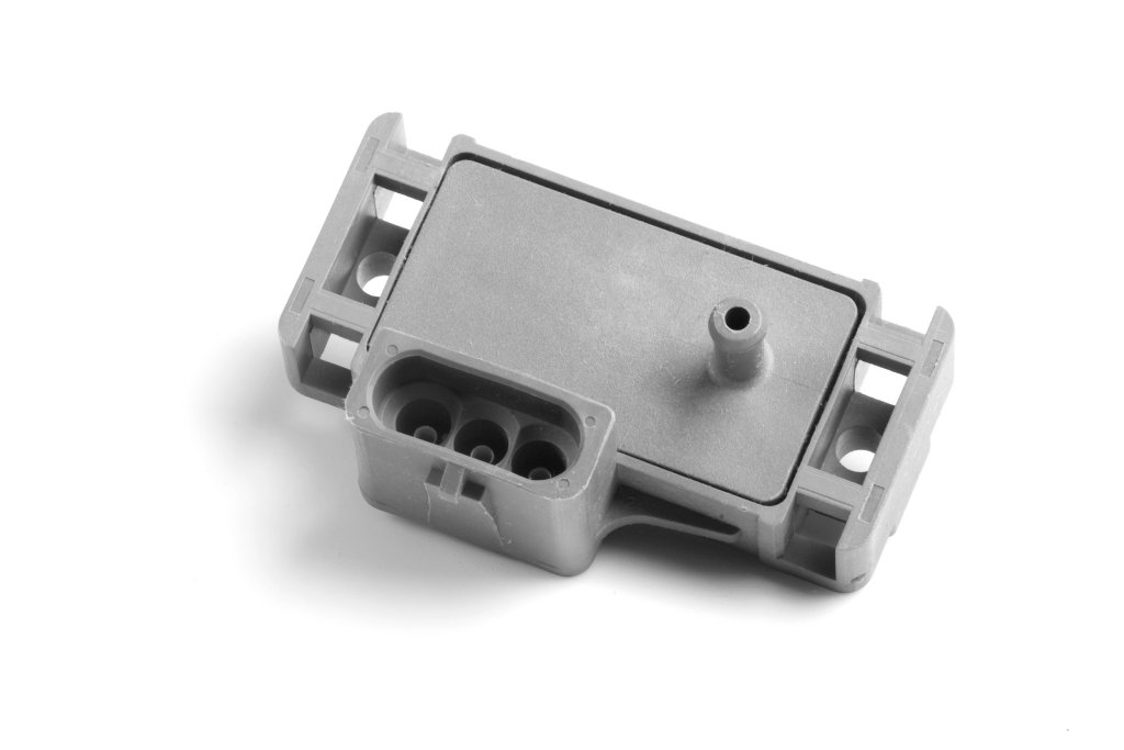
MAP Sensor |
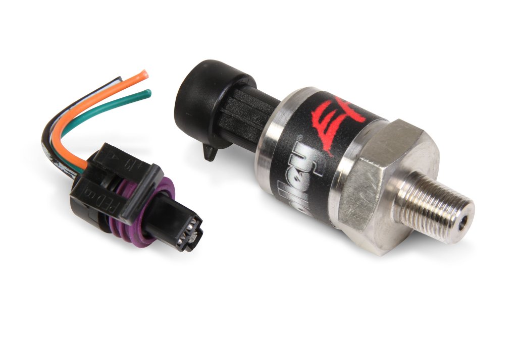
Pressure Sensors(2) |
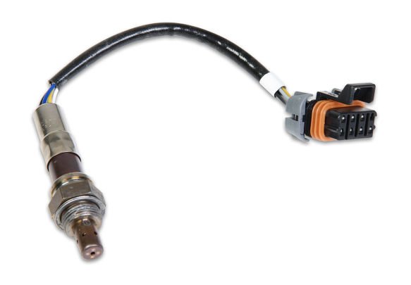
Wideband O2 Sensor |
Transmission Harness |
Auxillary Wiring Harness |
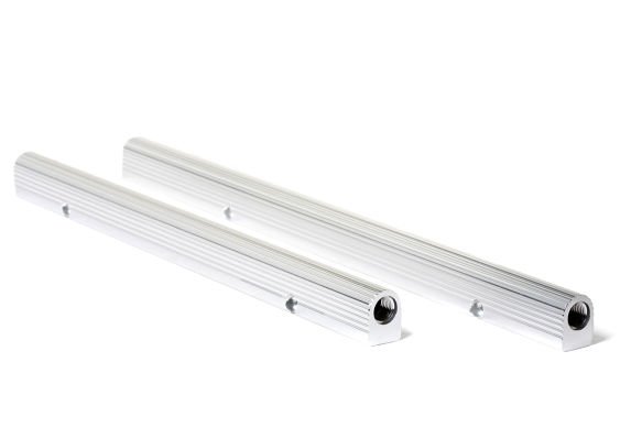 Fuel Rails |
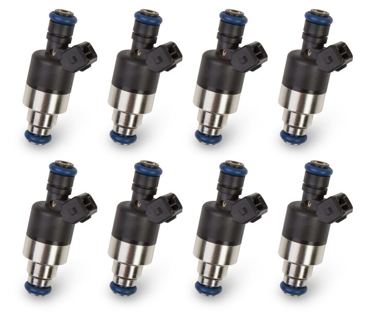
48 pph injectors |
Total parts cost was about $7046 which includes the parts shown above plus $743 for fuel lines (both hard and flexible), hose fittings, new plug wires, and a few miscellaneous pipe fittings.
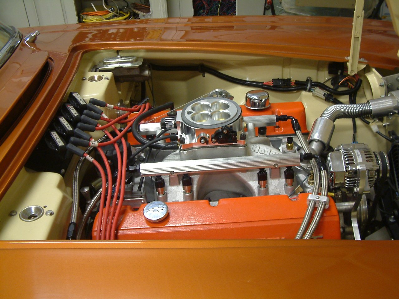
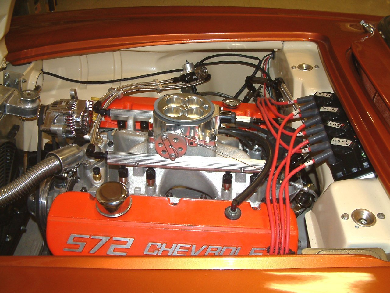
The Holley multiport manifold, throttle body, fuel injectors, waste fire coils, and fuel lines installed.
The only installation problem so far was an interference between the alternator and the fuel line fitting on the end of the fuel rail on the passenger side of the engine. I first shortened the fuel rail as much as possible, but this was not quite enough. The harmonic damper and water pump pulleys on my engine have two grooves so I was able to space out the alternator bracket and move the alternator belt to the forward groove to achieve enough clearance.
I also made a modification to the throttle linkage on the throttle body. The supplied throttle body cable connection is just a straight arm and I noticed when installing the throttle cable onto the linkage that the throttle shaft has to rotate approximately 90 degrees. This means that as the the lever rotates the angle of the throttle cable relative to the lever changes, making it harder to pull the lever. I made a circular pulley so that the amount of force required to open the throttle remains the same throughout the full travel.
The Holley system requires (or highly recommends) that several of the wiring harnesses be connected directly to the battery terminals. There is a 10ga. wiring harness that feeds +12v power and ground to the ECU, a +12v power and ground for the main wiring harness, and a +12v power and ground for the ignition coils. Since my battery is in the trunk these wires have to be snaked through to the rear of the car.
There are several "loose" wires in the wiring harnesses which are connected as follows:
Loose wires on main harness
12V Switched – Color = Red/White – Should be connected to a clean +12 volt power source. Power source should only be active when the ignition is on. Make sure source has power when engine is cranking as well. Not all sources apply power when the ignition switch is in “cranking” position.
12V Battery – Color = Red – Should be connected directly to the battery. There is a fuse holder attached that should contain a 20A rated fuse. This powers the fuel pump and fuel injectors.
12V Fuel Pump – Color = Green - Used to
directly power a fuel pump (+12 volt). Fully terminated harnesses utilize a relay to
supply this power. 14 gauge wire is used. Due to
this, it is not recommended for pumps that draw over 10-12 Amps to use this wire.
For high current pumps, use this wire to trigger a separate relay and use larger gauge
wire to feed the pump - 10 gauge is recommended. My fuel pump is rated at 14 amps
so I put another relay in the trunk close to the battery and fuel pump and wired the
signal wire in the Holley harness to trigger this relay.
Points Output – Color = White – Used to trigger a CD ignition box. Not used in my setup
Ignition/DIS Chassis Ground – Color = Black – Connect to a ground point that has excellent connectivity with both the engine and the battery.
“Coil – ” – Color = Yellow – Used for an RPM input signal when not controlling timing and NOT running a Capacitive Discharge (MSD) ignition system. See the ignition wiring section 8.0 for detailed wiring. WARNING! Connecting this wire to the coil of a CD ignition will damage the ECU. Not used in my setup
Loose wires on transmission harness
Brake Switch (Grey) – Wired to the brake light switch. This must be installed to a +12v source (as most brake light switches are). This input is used to unlock the torque converter when the brakes are applied.
Ground (Black) – Connect to a good chassis/engine ground source
Power (Red) – Supplies power to the transmission solenoids. This should be connected to a +12v switched power source (must be capable of supplying 5 amps). NOTE: The power supplying this wire must NOT be tied to the same point that the ECU switched power wire (red/white wire) is connected to. If they are tied together, the transmission power will back-feed power to the ECU and the ECU/engine will not shut off when the key is turned off. Use a relay or separate switched ignition power pickup point to supply power to the transmission harness.
There is no "loose" wire supplied in the Holley harness for a tachometer signal, however the Dominator ECU can be programmed to supply this signal.